
Electric tricycle battery packs
For electric tricycles used in transport or delivery, we discuss pack configuration around payload, operating conditions, mounting space and electrical interfaces.
Discuss your project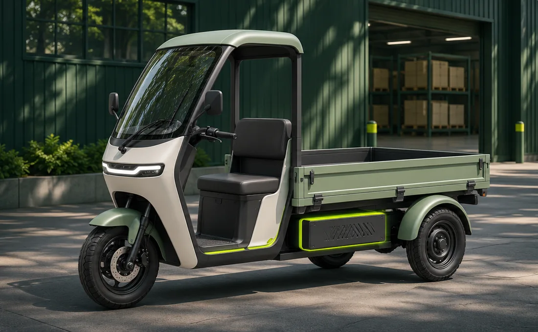
Electric Tricycle Battery Pack Selection and Integration
Engineering selection reference. The agreed sample pack and specification define voltage, capacity, interfaces, performance and scope of supply.
Record the actual duty cycle
For cargo tricycles, capture payload, grades, operating hours, stop frequency and reserve for the return trip. For passenger vehicles, include loaded starts and low-speed climbs. Measure energy use on typical and heavier routes.
Platform voltage and equipment limits
Electric tricycle platforms commonly include 48 V, 60 V and 72 V examples. Check the controller’s full operating window and cutoffs, maximum charging voltage and auxiliary electronics. Share photographs of the existing battery and controller nameplates if technical drawings are unavailable.
Size energy from measured Wh/km
Multiply measured Wh/km by the target distance to estimate usable energy for the route. Convert that to nominal energy using the usable fraction agreed for the project. Record payload, road conditions, speed and temperature alongside the result.
Separate continuous and peak current
Long grades at full payload govern sustained current and heat. Repeated starts govern peak current, duration and recovery intervals. Use logs on the battery side of the controller. Phase current and rated motor watts provide context.
Enclosure, fit and servicing
Share net compartment dimensions, fixing points, cable exit direction and clearance to remove the pack. Discuss sealing, abrasion protection and mounting against splash, washing, vibration and the planned service method. Agree enclosure protection after validation.
Charging and fleet turnaround
Use shift energy, return time, concurrent charge points and supply capacity to plan turnaround. For a swappable design, evaluate connector cycle life, mechanical latching and interlocks as part of the system.
Loaded Sample Pack Validation
- Measure pack current, terminal voltage and temperature during repeat launches and sustained climbs at full payload. Check for excessive sag, derating and unexpected cutoffs.
- Measure usable energy on the representative route. Record payload, speed, temperature and start and end state of charge so later tests can reproduce the result.
- Validate restraint, harness wear, connector use and charge interlock against the vehicle’s operating and service environment. Capture the acceptance conditions in the specification.
Technical Reading and Project Support
What to prepare
- Vehicle model, intended use and duty cycle
- Battery bay dimensions, mounting points and access
- Voltage requirements, load, connectors and charging interface
- Sample needs, estimated volume and delivery timing
Discuss your project
The details you submit will be used to follow up on your project inquiry.